Spool Drawings– Achieving Precision in Fabrication
Source: Autodesk
Every construction project comprises multiple services. These range from structures to networks of ducts and pipes. And a successful project integrates them without overlapping or clashes. Spool drawings are a guide to these piping systems to ensure clash-free installation. These are used for plumbing, HVAC, and MEP fabrications.
Let’s understand these drawings and how they benefit the typical AEC workflow.
Decoding Spool Drawings and Their Purpose/ What are Spool Drawings?
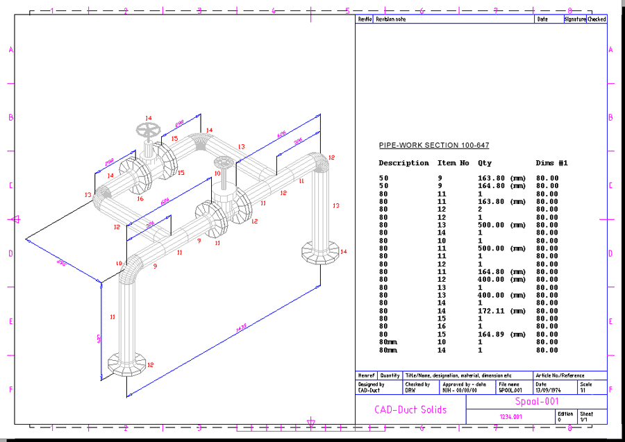
Spool drawings exhibit every minute detail of prefabricated components used for a piping system. It displays information ranging from material specifications to dimensions for a particular segment of a piping system.
What is the Purpose of Spool Drawing?
Convey Sizes and Dimensions
These comprise accurate length, diameter, thickness, sizes, and types of fittings and valves.
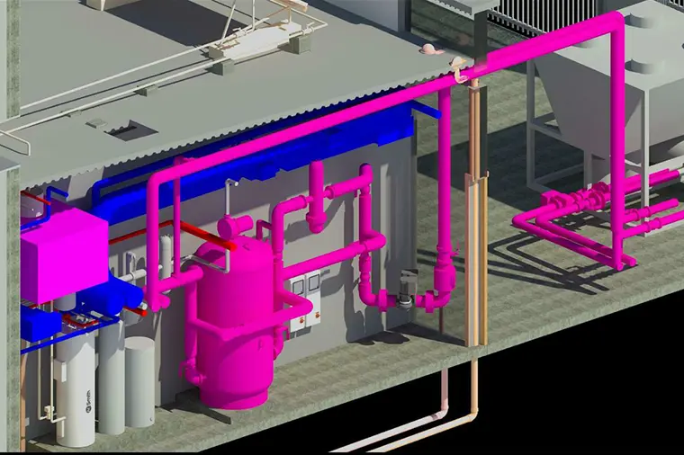
Showcase the Routing and Layout of Pipes
It gives a clear layout, mentioning the location of fittings, valves, and other components.
Specify the Materials
These drawings give clear information on the type and grade of material used.
Illustrate Welding and Joining Details
Information regarding the joinery and welding of a pipe spool is conveyed through these drawings.
Mark the Types of Hangers and Supports
These illustrate the location and type of hangers and supports used in the piping system.
Critical Role of Spool Drawings in AEC Projects
These help seamlessly translate the details from BIM to physical construction. Here are the significant purposes catered to by these drawings:
Guiding the Fabrication Process
The comprehensive details on dimensions, welding specifications, materials, and other critical guide the fabricators. It clarifies the manufacturing of every unit for piping or ducting systems.
Promising Coordination
Precise and detailed drawings bridge the gap between digital models and on-site construction. It guarantees that every system seamlessly fits with the other to minimize clashes.
A Go-to Reference Point for Installation
The details on fitting and integrating a particular unit into the overall system guide the installation process. It leads to error-free assembly of the entire piping system.
Driving Optimization for Cost
Owing to the precision in details, these ensure error-free assembly. Thus minimizing the cost overruns, cutting down wastage, and enhancing efficiency.
Bridging the Communication Gap
These drawings guarantee seamless communication of information amongst the stakeholders involved. The precision in detailing offers clarity on the design and technical details.
How are Spool Drawings Addressing the Common AEC Challenges?
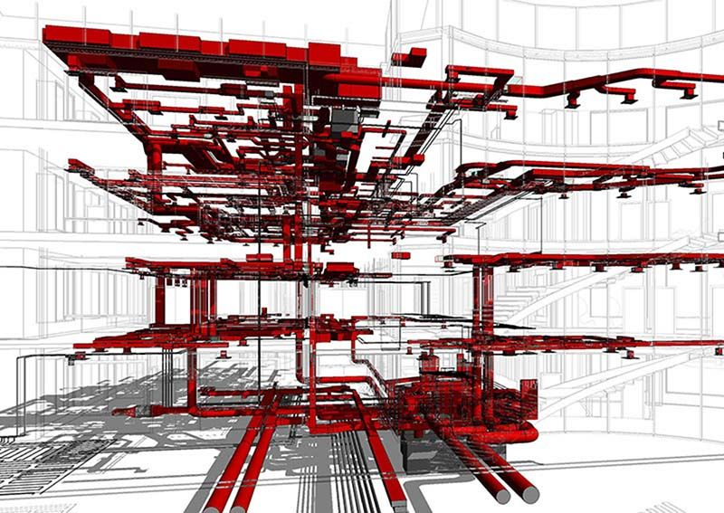
Tackling the Clashes
Overlapping the layouts and identifying clashes is a daunting task. This is where BIM tools help. These help generate comprehensive drawings and their integration into the 3D model. The real-time information conducts clash detection. It then highlights the issues and helps resolve clashes before on-site construction.
Overcoming the Dimensional Inaccuracies
Inaccuracy is one of the critical challenges associated with traditional AEC workflows. However, designers can meet unparalleled accuracy with an advanced BIM approach.
Defining Welding Standards
Typically, AEC workflows don’t define welding details for pipes. It can lead to structural inefficiency and compromise safety. This is where spool drawings come into the picture. These adhere to the industry standards and define welding details through comprehensive documentation.
A Step-by-Step Guide to Create Spool Drawings in Revit

Source: Autodesk
Step 1: Open the Revit model.
Step 2: Create item number tags per the accessories, pipes, and fittings. Make sure to give a unique number to every item and provide a bill of materials in the sheet. The bill of materials must have detailed information on every item.
Step 3: Create a pipe and pipe fitting schedule by mentioning the item number and its respective size, description, name, total count, and other critical parameters. Filter the pipe schedule by assembly name for organized information.
Step 4: The next step is to group the items. You can customize it based on the preferred settings.
Step 5: After creating spools, start making a spool map by defining the color for every distinct spool.
Step 6: Pick the section of pipe where the spool will be added. Click on the modify tag and place the desired assembly.
With this simple procedure, you can effortlessly build a spool sheet offering clarity of services.
Seamless Services with Unparalleled Efficiency

A construction process becomes faster and smoother with detailed information. With these comprehensive drawings, one can rest assured of enhanced quality, seamless physical workflow, and lesser wastage.
Our team at AEODC generates comprehensive spool drawings that serve as the perfect guide for fabricators during the prefabrication and assembly stages. To know more, https://www.aeodc.com/services/shop-spool-drawing-generation/
FAQs
What does the term spooling mean in BIM?
A spool refers to the assembly of pipes and related components for accurate pre-fabrication. Once fabricated, these are sent to the site for easy installation.
What is the role of a spool in piping?
It is used as a connection between the two other parts of a piping system.
What are the major perks of using BIM for spool drawings?
It enhances accuracy, minimizes the chances of clash, improves efficiency, and helps in seamless coordination amongst the teams.
Which software supports the creation of spool drawings?
Revit, AutoCAD, Solidworks, and Fusion 360.
Source URL:


Comments
Post a Comment